Share
Pin
Tweet
Send
Share
Send

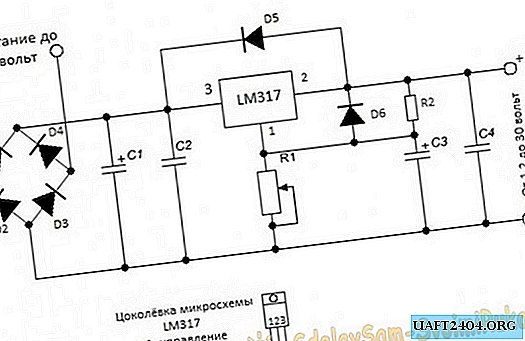
The power supply circuit is designed for voltages up to 40 volts of alternating current, and the output can be obtained from 1.2 to 30 volts of constant, stabilized voltage. Adjustment from minimum to maximum by potentiometer is very smooth, without jumps and dips. Output current up to 1.5 amperes. If the current consumption is not planned above 250 milliamps, then a radiator is not needed. When consuming a greater load, place the chip on a heat-conducting paste to the radiator with a total dispersion area of 350 - 400 or more, square millimeters. The selection of a power transformer should be calculated on the basis that the voltage at the input to the power supply should be 10 - 15% more than you plan to receive at the output. The power of the supply transformer is better to take with a good margin, in order to avoid excessive overheating and it is imperative to put a fuse selected at the input to protect it from possible troubles.
We, for the manufacture of this desired device, need the details:
- Chip LM317 or LM317T.
- The rectifier assembly is almost any or four separate diodes per current of at least 1 ampere each.
- Capacitor C1 from 1000 μF and above with a voltage of 50 volts, it serves to smooth out surges of the supply network and the larger its capacity, the more stable the output voltage will be.
- C2 and C4 - 0.047 MkF. On the cap of the capacitor is the number 104.
- C3 - 1MkF and more with a voltage of 50 volts. This capacitor can also be used with a larger capacity to increase the stability of the output voltage.
- D5 and D6 are diodes, for example 1N4007, or any others for a current of 1 amp or more.
- R1 - potentiometer for 10 Com. Any type, but certainly good, otherwise the output voltage will "jump".
- R2 - 220 Ohms, power 0.25 - 0.5 watts.
Before connecting to the supply voltage circuit, be sure to check the correct installation and soldering of the circuit elements.
Assembling an adjustable stabilized power supply
I assembled on a regular breadboard without any etching. I like this method because of its simplicity. Thanks to him, the circuit can be assembled in a matter of minutes.


Power supply check
By rotating the variable resistor, you can set the desired output voltage, which is very convenient.


Power supply test video attached
Share
Pin
Tweet
Send
Share
Send


